


SIEMENS Processor Module Overview
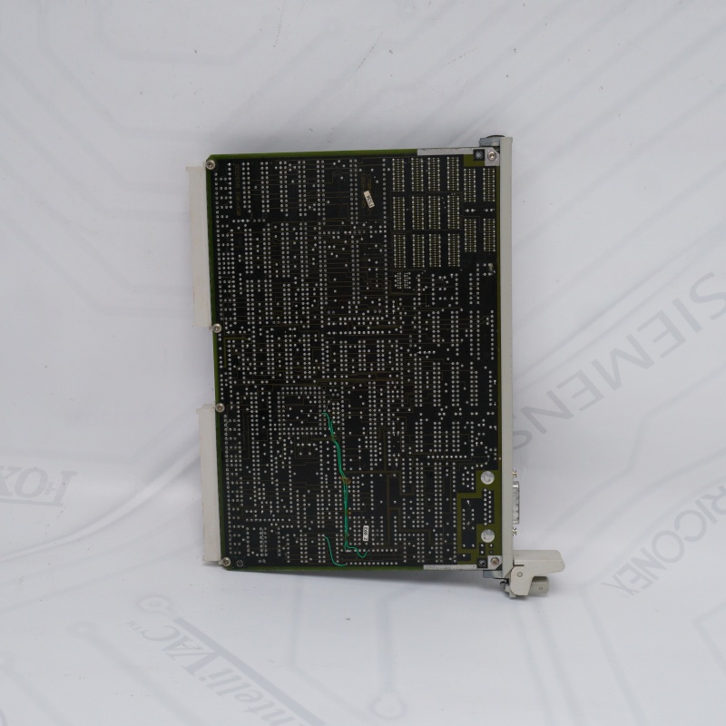
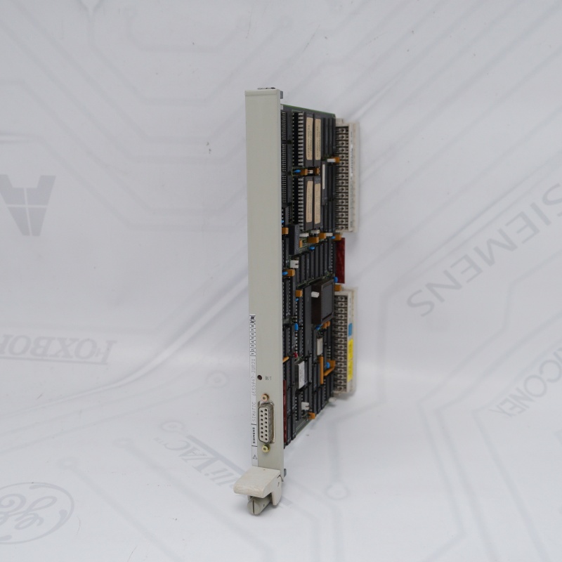
The Siemens 6ES5947-3UR21 (CPU 947R) is an obsolete central processing unit designed for high-availability industrial automation.
SIEMENS Processor Module Core Purpose: Engineered exclusively for the S5-155H fault-tolerant/redundant PLC system.
Redundant Control: Operates in dual-processor setups (subunits A and B) with seamless failover to prevent factory downtime.
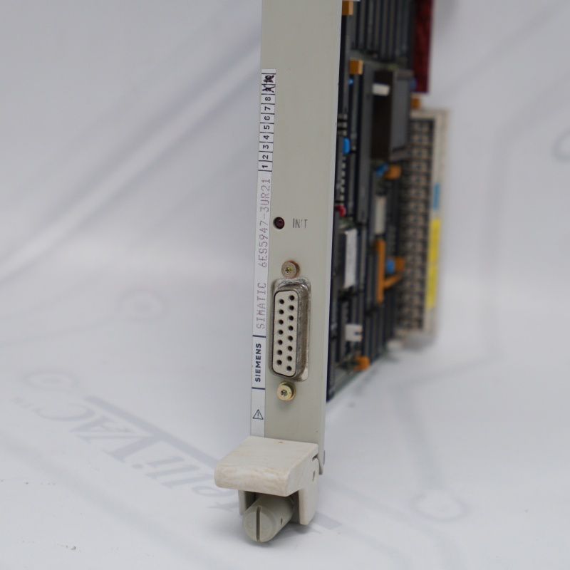
Processor Module Key Specs: Built-in 128 KB memory and 1x TTY (20mA current loop) programming interface.
Processor Module Current Status: Discontinued since 1994. Available only as refurbished/used stock.
Processor Module Critical Note: Replacement modules must match the exact firmware revision level of the companion CPU to sync properly.
If you want to more details about SIEMENS Processor Module,please contact me without hesitate.Email:sales@sparecenter.com
SIEMENS Processor Module Test Procedure
1. SIEMENS Processor Module Reset Test
Insert module and trigger Overall Reset.
Pass: STOP LED flashes rapidly, confirming RAM and logic health.
2. SIEMENS Processor Module Communication Test
Connect via TTY cable using STEP 5 software.
Pass: Successful online connection and error-free OB1 download.
3. SIEMENS 6ES5947-3UR21 Standalone Run
Boot with active I/O modules (RUN LED solid green).
Pass: Mid-run I/O disconnection triggers correct OB fault logs.
4. 6ES5947-3UR21 SIEMENS Redundancy Failover
Install two identical-firmware 6ES5947-3UR21 SIEMENS units into an S5-155H rack.
Pass: Cutting Master power triggers microsecond-level seamless Standby takeover.
Reasons for choosing Spare Center
Massive Stock
Over 1M products ready for same-day shipping.
Global Support
Multilingual team serving 100+ countries.
Guaranteed Quality
Original origin testing with third-party verification.
Flexible Shipping
Global delivery via DHL, FedEx, TNT, and UPS.
SIEMENS Processor Module FAQ
Q1: What is the primary industrial application of the 6ES5947-3UR21 SIEMENS processor?
A1: The SIEMENS 6ES5947-3UR21 is a legacy high-performance CPU module engineered exclusively for the SIMATIC S5-155H fault-tolerant automation platform. It is deployed in critical production environments—such as chemical processing, power generation, and continuous manufacturing lines—where unexpected system downtime is prohibited and dual-processor redundancy is mandatory.
Q2: Can I pair a 6ES5947-3UR21 SIEMENS module with any other S5 CPU in a redundant configuration?
A2: No. For the S5-155H fault-tolerant architecture to function, the SIEMENS 6ES5947-3UR21 must be paired with an identical companion processor or compatible partner module (such as the CPU 946R) within the same synchronized central controller. Furthermore, both subunits must maintain the exact same hardware and firmware operating system revisions to prevent synchronization blocks.
A2: No. For the S5-155H fault-tolerant architecture to function, the SIEMENS 6ES5947-3UR21 must be paired with an identical companion processor or compatible partner module (such as the CPU 946R) within the same synchronized central controller. Furthermore, both subunits must maintain the exact same hardware and firmware operating system revisions to prevent synchronization blocks.
Q3: Why does my replacement 6ES5947-3UR21 fail to synchronize with the existing master CPU?
A3: This synchronization failure typically stems from a firmware revision mismatch. If your newly sourced SIEMENS 6ES5947-3UR21 has an older operating system level (e.g., prior to Revision Level 10) than your active unit, the internal synchronization registers will reject the link; upgrading the EPROM chipsets on the older SIEMENS 6ES5947-3UR21 to match Revision Level 10 is required to resolve this issue.
A3: This synchronization failure typically stems from a firmware revision mismatch. If your newly sourced SIEMENS 6ES5947-3UR21 has an older operating system level (e.g., prior to Revision Level 10) than your active unit, the internal synchronization registers will reject the link; upgrading the EPROM chipsets on the older SIEMENS 6ES5947-3UR21 to match Revision Level 10 is required to resolve this issue.
Q4: What are the communication capabilities and programming interfaces built into the 6ES5947-3UR21?
A4: The 6ES5947-3UR21 SIEMENS features an integrated 20mA current loop (TTY) communications interface accessible via a standard 15-pin Cannon D-sub socket. This physical port allows the SIEMENS 6ES5947-3UR21 to interface directly with industrial Programmer Units (PG) running STEP 5 software, legacy Operator Panels (OP), or PC-based SCADA systems utilizing proper protocol converters.
A4: The 6ES5947-3UR21 SIEMENS features an integrated 20mA current loop (TTY) communications interface accessible via a standard 15-pin Cannon D-sub socket. This physical port allows the SIEMENS 6ES5947-3UR21 to interface directly with industrial Programmer Units (PG) running STEP 5 software, legacy Operator Panels (OP), or PC-based SCADA systems utilizing proper protocol converters.
Q5: How can I perform a hardware factory reset on a faulted 6ES5947-3UR21 module?
A5: To clear memory errors on the 6ES5947-3UR21 SIEMENS, remove the backup battery, insert the unit into a powered UR1/UR2 rack, and toggle the mode switch to STOP. Hold the "Overall Reset" spring-loaded switch downward while quickly switching the mode selector from STOP to RUN and back to STOP; the STOP LED on the 6ES5947-3UR21 SIEMENS will flash rapidly to confirm successful RAM and system data block clearing.
A5: To clear memory errors on the 6ES5947-3UR21 SIEMENS, remove the backup battery, insert the unit into a powered UR1/UR2 rack, and toggle the mode switch to STOP. Hold the "Overall Reset" spring-loaded switch downward while quickly switching the mode selector from STOP to RUN and back to STOP; the STOP LED on the 6ES5947-3UR21 SIEMENS will flash rapidly to confirm successful RAM and system data block clearing.
Other Modules
| 6ES7322-1BL00-0AA0 | 6ES7951-0KF00-0AA0 |
| 6ES7392-1AM00-0AA0 | 6AV3503-1DB10 |
| 6ES7153-2BA02-0XB0 | 6ES7421-1BL01-0AA0 |
| 6ES7321-1BH02-0AA0 | 6ES7511-1AK01-0AB0 |
| 6ES7531-7KF00-0AB0 | 6ES5948-3UR23 |
| 6EP1334-3BA10 | 500-033260 |
| 6EP1336-3BA00 | 6ES7221-1BH32-0XB0 |
| 6ES7392-1AJ00-0AA0 | 6ES7131-4BD01-0AA0 |
| 6ES7214-1AG40-0XB0 | 6ES7532-5HF00-0AB0 |
| 6ES7422-1BL00-0AA0 | 6AV6643-0DD01-1AX1 |
| 6ES7332-5HF00-0AB0 | 6ES7222-1BH32-0XB0 |
| 6SE7033-5GJ84-1JC0 | 6ES5465-4UA12 |
| 6ES7331-7KF02-0AB0 | 6AV6647-0AK11-3AX0 |
| 6AV2124-0MC01-0AX0 | 6ES7412-2XG00-0AB0 |
| 6AV3627-1LK00-1AX0 | 6ES7522-1BH00-0AB0 |

Email: sales@sparecenter.com