


24646-06-04-03 BENTLY NEVADA Highlight
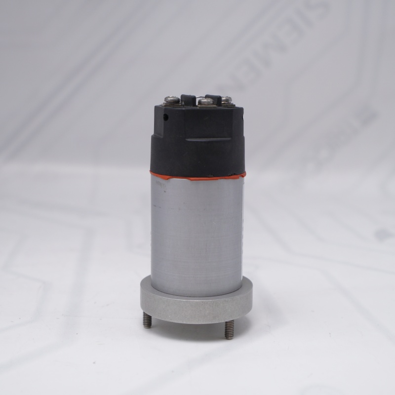
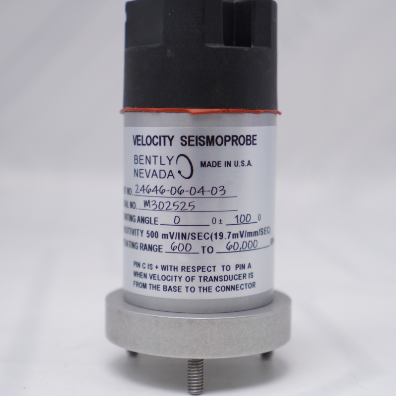
24646-06-04-03 BENTLY NEVADA Type: Seismoprobe Velocity Transducer (Moving-coil design)
24646-06-04-03 BENTLY NEVADA Sensitivity: 500 mV/in/s (19.7 mV/mm/s)
Frequency Range: 600 to 60,000 CPM (10 Hz to 1 kHz)
Orientation: 0° ± 100° Mounting Angle
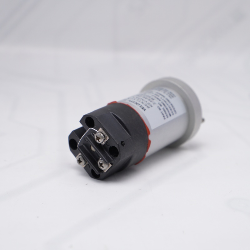
Connection: Top-Mount Terminal Block with protective sleeve
Application: Casing & bearing housing vibration monitoring on rotating machinery
BENTLY NEVADA Velocity Seismoprobe Images

BENTLY NEVADA Velocity Seismoprobe

BENTLY NEVADA Velocity Seismoprobe

24646-06-04-03 Velocity Seismoprobe
24646-06-04-03 Velocity Seismoprobe FAQ
Q1: What is the primary function of the Bently Nevada 24646-06-04-03 transducer?
A1: The Bently Nevada 24646-06-04-03 is a moving-coil velocity seismoprobe transducer designed to measure absolute casing, bearing housing, or structural vibration on rotating machinery such as turbines, pumps, and fans.
Q2: What are the key technical specifications of the 24646-06-04-03 model?
A2: The Bently Nevada 24646-06-04-03 features a standard sensitivity of 500 mV/in/s (19.7 mV/mm/s), an operating frequency range of 600 to 60,000 CPM (10 Hz to 1 kHz), a 0° ± 100° mounting angle, and a top-mount terminal block electrical connection.
Q3: What does the suffix "-06-04-03" represent on the 24646-06-04-03 sensor?
A3: For the Bently Nevada 24646-06-04-03, "-06" defines the 10 Hz minimum operating frequency, "-04" specifies the top-mount terminal block connector option, and "-03" indicates the factory hazardous area approval rating (e.g., ATEX/IECEx/CSA intrinsically safe).
Q4: How should the polarity be wired for the Bently Nevada 24646-06-04-03?
A4: When wiring the Bently Nevada 24646-06-04-03, Pin C is defined as the positive (+) terminal with respect to Pin A. This polarity is observed when the velocity of the transducer moves from the base toward the connector.
Q5: What are the mounting orientation restrictions for the Bently Nevada 24646-06-04-03?
A5: The 24646-06-04-03 Velocity Seismoprobe has a specified mounting angle of 0° ± 100°. This means the sensor must be installed within 100 degrees of its calibrated vertical orientation to ensure the internal moving-coil mechanism operates with maximum accuracy and minimal cross-axis error.
Other Modules
| 330104-15-23-10-02-00 | 330878-50-00 |
| 330104-19-25-10-11-05 | 330103-00-12-10-01-00 |
| 330103-00-05-10-02-05 | 330103-00-16-10-01-00 |
| 330103-00-18-05-02-05 | RS901104-03-050-10-01 R200602-400808 |
| 330130-045-02-05 | 330105-02-12-50-02-00 |
| 330101-00-08-05-02-05 | 350500-00-00-00-11-00 |
| 330130-085-00-05 | 330190-080-01-00 |
| 125388-01 | 3500/77M 140734-07 |
| 128275-01/128275-01F 130944-01 | 2201/03-01 |
| 330780-91-00 | 1900/65 |
| 330103-00-14-10-01-00 | 21747-080-00 |
| 330730-080-02-00 | 330730-080-01-00 |
| 330104-05-13-10-02-00 | 330930-060-00-00 |
| 3500/23E | 125388-01H 125388-01 |
| 3500/15E | 125720-02 |
| 136711-01 | 138708-01 |
| 330703-000-040-10-11-00 | 330104-00-08-10-02-00 |
| 330705-02-18-10-02-00 | 330105-02-12-05-02-CN |
| 990-04-70-02-00 | 330101-10-27-05-02-05 |
| 330703-000-070-10-02-00 | 330130-045-00-CN |

Contact Us
Email: sales@sparecenter.com