


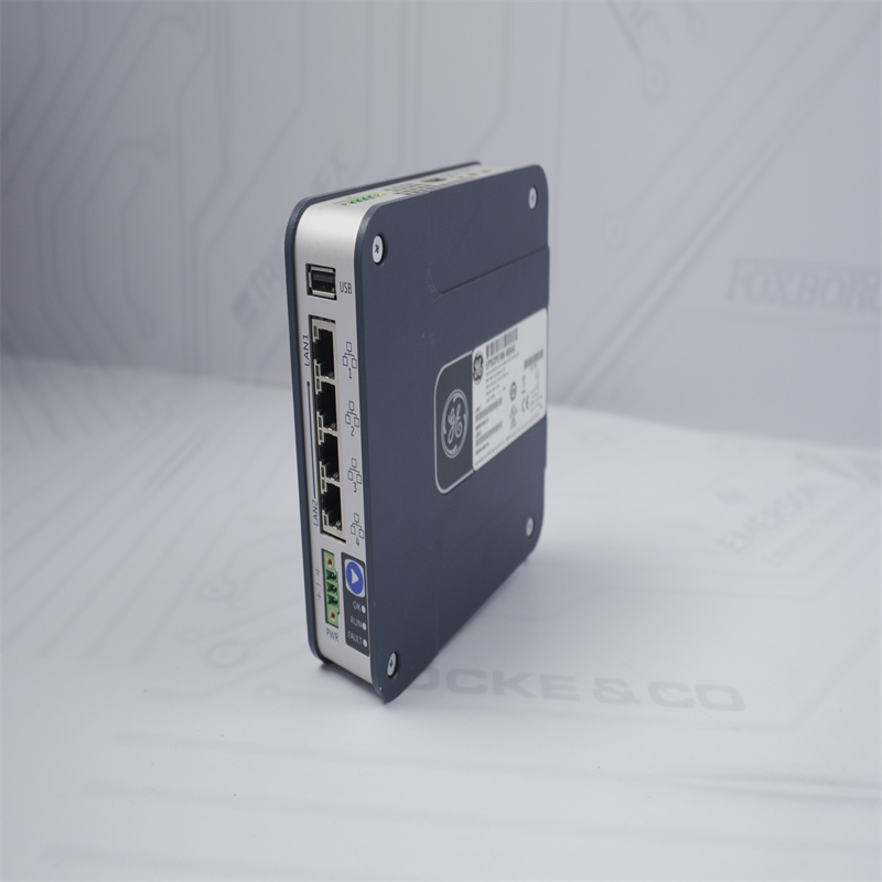
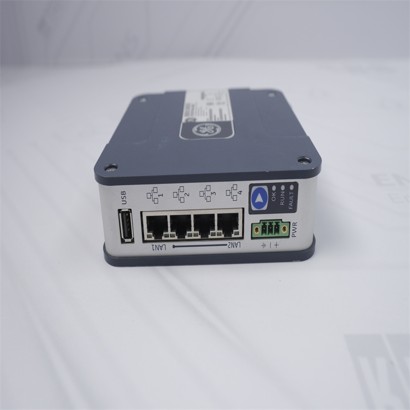
LED Indicators (LEDs)
| LED | LED State | Operating State |
OK | On Green | PLC has passed its power-up diagnostics and is functioning properly |
| Off | Power is not applied or PLC has a problem. | |
| Blinking; All other LEDs off | PLC in STOP/Halt state; possible watchdog timer fault. If the programmer cannot connect, cycle power and refer to the fault tables. | |
RUN | On Green | PLC is in RUN mode. |
| Off | PLC is in STOP mode. | |
| Blinking; All other LEDs off | Indicates that PLC has encountered a fatal error and is blinking the error code. | |
| Fault | On Green | PLC is in STOP/Faulted mode: a fatal fault has occurred. |
| Off | No fatal faults detected. |
If you want to more details,please contact me without hesitate.Email:sales@sparecenter.com
Hardware Installation
| Initial Checks |
| Upon receiving your equipment, carefully inspect all shipping containers for damage. If any part of the system is damaged, notify the carrier immediately. The damaged shipping container should be saved as evidence for inspection by carrier. |
| As the consignee, it is your responsibility to register a claim with the carrier for damage incurred during shipment. GE Automation & Controls will fully cooperate with you, however, should such action be necessary. |
| After unpacking the equipment, record all serial numbers. Serial numbers are required if you should need to contact Customer Care during the warranty period. All shipping containers and all packing material should be saved should it be necessary to transport or ship any part of the system. |
| Verify that all components of the system have been received and that they agree with your order. If the system received does not agree with your order, contact Customer Care. |
| Thermal Requirements: |
| When mounting the CPE100, allow a minimum clearance of 50mm on the left & right side of the unit and a minimum clearance of 100mm on the top & bottom sides. |
Instructions to mount the CPE100 on a Panel
Attach the panel mount plate to the rear side of CPE100 using the four M3 screws supplied with the adapter.
Fasten the tabs of panel mount adapter in the appropriate location of panel with the four screws. The screw size used for each panel mount tab should not exceed M5.
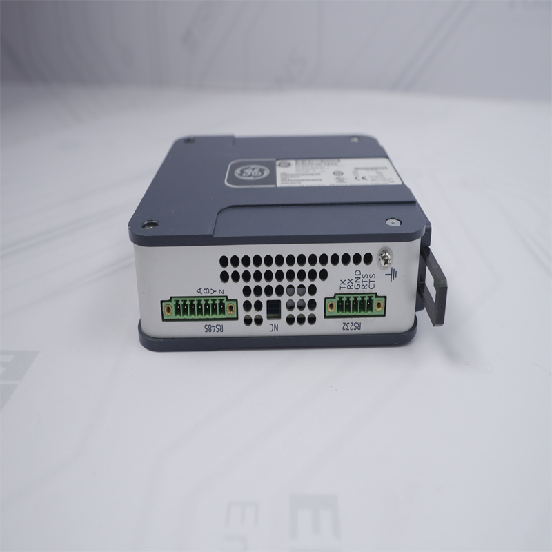
Grounding
Proper grounding of the CPE100 is essential using the provided ground terminal as shown in the below figure. Use a 16-22 AWG braided wire with lugs to connect the ground terminal of CPE100 to DIN Rail.
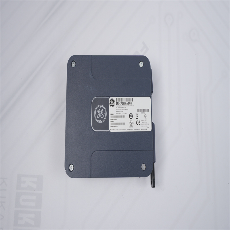
Product Photos


Other Modules
GE EPSCPE100-ABAG GE Programmable Control Products GE EPSCPE100 EPSCPE100-ABAG-CN GE EPSCPE100-ABAG GE Programmable Control Products GE EPSCPE100 EPSCPE100-ABAG-CN GE EPSCPE100-ABAG GE Programmable Control Products GE EPSCPE100 EPSCPE100-ABAG-CN GE EPSCPE100-ABAG GE Programmable Control Products GE EPSCPE100 EPSCPE100-ABAG-CN GE EPSCPE100-ABAG GE Programmable Control Products GE EPSCPE100 EPSCPE100-ABAG-CN GE EPSCPE100-ABAG GE Programmable Control Products GE EPSCPE100 EPSCPE100-ABAG-CN GE EPSCPE100-ABAG GE Programmable Control Products GE EPSCPE100 EPSCPE100-ABAG-CN GE EPSCPE100-ABAG EPSCPE100-ABAG-CN GE EPSCPE100-ABAG EPSCPE100-ABAG-CN GE EPSCPE100-ABAG EPSCPE100-ABAG-CN GE EPSCPE100-ABAG EPSCPE100-ABAG-CN General ElectricIS220PDOAH1BDiscrete Output Pack GE UR7CM GE UR7CM GE UR7CM GE UR7CM GE UR7CM GE UR7CM GE UR7CM General Electric UR7CM General Electric UR7CM General Electric UR7CM GE Multilin UR7CM GE Multilin UR7CM GE Multilin UR7CM GE Multilin UR7CM GE Digital Input Module GE Digital Input Module GE Digital Input Module GE UR7CM GE UR7CM GE UR7CM GE UR7CM GE UR7CM GE UR7CM GE UR7CM GE Control Board Module GE Control Board Module GE Control Board Module GE Control Board Module General Electric IS215WEPAH2BA General Electric IS215WEPAH2BA General Electric IS215WEPAH2BA |

Mobile/what's app: +852 6980 6006
Email: sales@sparecenter.com