

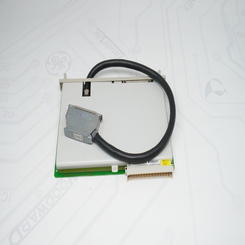
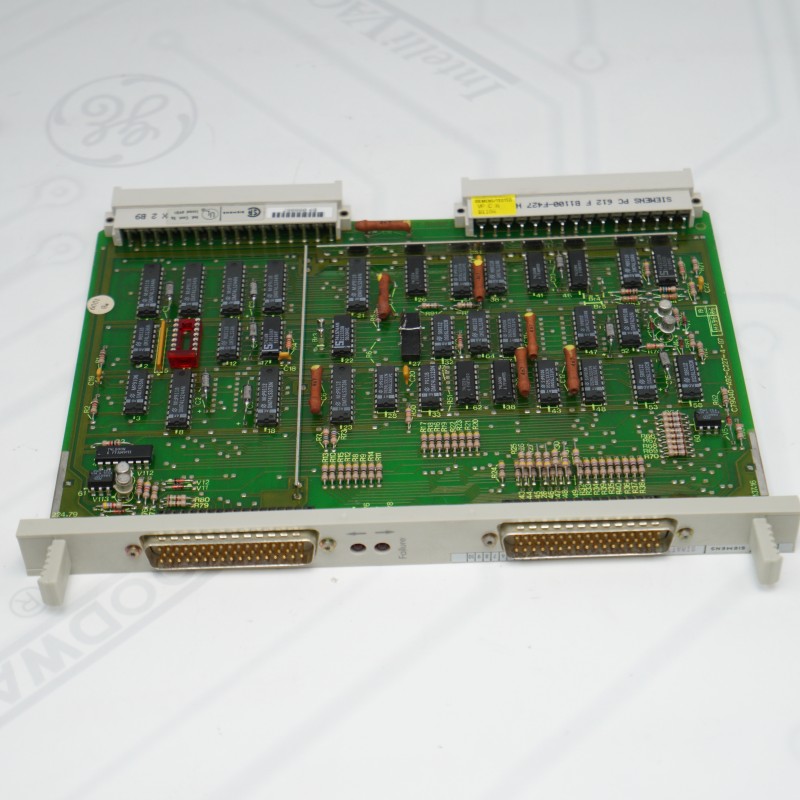
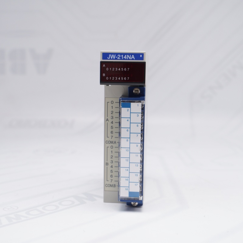
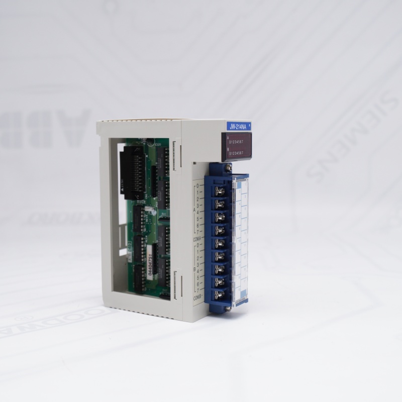
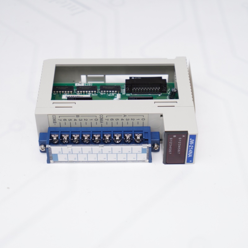
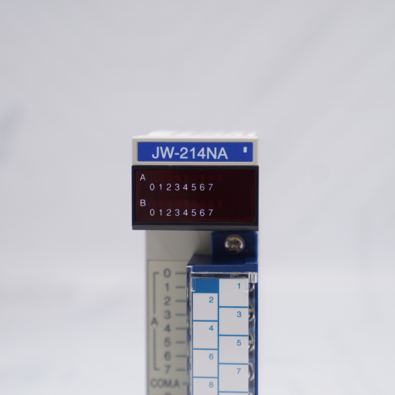
JW-214NA Primary Applications
Conveyor Product Tracking: JW-214NA SHARP(SHARP JW-214NA) captures photoelectric sensor signals to locate items on moving assembly lines.
Machine Over-travel Safety: JW-214NA SHARP(SHARP JW-214NA) reads physical limit switch inputs to prevent robotic arms from crashing.
Operator Panel Control: JW-214NA SHARP registers manual command signals from push-buttons, selectors, and e-stops.
Pneumatic Cylinder Monitoring: JW-214NA SHARP tracks magnetic switches to confirm if air pistons are extended or retracted.
Part Presence Verification: JW-214NA SHARP validates whether a component is correctly loaded before automated assembly begins.
High-Speed Batch Counting: JW-214NA SHARP connects to proximity sensors to tally completed products for packaging units.
JW-214NA SHARP Testing Process
JW-214NA SHARP Bench Mount
Plug the module into the PLC rack with power off. Turn on the main PLC rack power.
JW-214NA SHARP Hardware Test
Jumper 24V DC power to an input terminal point. Ensure the corresponding channel indicator LED turns on.
JW-214NA SHARP Software Check
Open the PLC programming software on your PC. Confirm the specific input address value changes from 0 to 1.
JW-214NA DC Digital Input Module FAQ
Q1: What is the primary function of the SHARP JW-214NA module within a control system?
A1: The SHARP DC Digital Input Module functions as a 16-point digital input peripheral module designed to convert external high-voltage field signals into logic-level data for processing by SHARP JW series programmable logic controllers.
A1: The SHARP DC Digital Input Module functions as a 16-point digital input peripheral module designed to convert external high-voltage field signals into logic-level data for processing by SHARP JW series programmable logic controllers.
Q2: What input voltage specifications are required to trigger a channel on the SHARP JW-214NA?
A2: The SHARP DC Digital Input Module features dual-rated compatibility, accepting both 12V DC and 24V DC nominal input voltages with an operational tolerances range typically between 20.4V DC and 26.4V DC.
A2: The SHARP DC Digital Input Module features dual-rated compatibility, accepting both 12V DC and 24V DC nominal input voltages with an operational tolerances range typically between 20.4V DC and 26.4V DC.
Q3: How does the SHARP JW-214NA protect internal PLC processing circuitry from external electrical faults?
A3: The SHARP DC Digital Input Module utilizes integrated photocoupler isolation between its field-side terminal block and the backplane connector, preventing high-voltage transients and electrical noise from damaging the host PLC.
A3: The SHARP DC Digital Input Module utilizes integrated photocoupler isolation between its field-side terminal block and the backplane connector, preventing high-voltage transients and electrical noise from damaging the host PLC.
Q4: Can a faulty channel on a SHARP JW-214NA be hot-swapped while the PLC rack is powered on?
A4: No, replacing a JW-214NA DC Digital Input Module requires complete system power de-energization before extraction to prevent backplane arcing or permanent damage to the PLC CPU module.
A4: No, replacing a JW-214NA DC Digital Input Module requires complete system power de-energization before extraction to prevent backplane arcing or permanent damage to the PLC CPU module.
Q5: What should be verified if a field sensor is active but the channel LED on the SHARP JW-214NA remains off?
A5: You must measure the voltage across the specific input terminal and the common (COM) terminal of the SHARP DC Digital Input Module using a multimeter to confirm that a minimum threshold of 12/24V DC is physically reaching the module.
A5: You must measure the voltage across the specific input terminal and the common (COM) terminal of the SHARP DC Digital Input Module using a multimeter to confirm that a minimum threshold of 12/24V DC is physically reaching the module.
Q6: What software steps are necessary to verify that a SHARP JW-214NA is communicating with the CPU?
A6: You must open the SHARP PLC ladder programming software, access the I/O table configuration register assigned to the specific slot of the SHARP DC Digital Input Module, and monitor the real-time status of the corresponding memory bits.
A6: You must open the SHARP PLC ladder programming software, access the I/O table configuration register assigned to the specific slot of the SHARP DC Digital Input Module, and monitor the real-time status of the corresponding memory bits.
If you want to more details about JW-214NA DC Digital Input Module,please contact me without hesitate.Email:sales@sparecenter.com
Other Modules
| FBM203 P0914SV | FBM218 P0922VW |
| FBM206 P0916CQ | FBM239 P0927AG |
| FBM207C P0917GY | FBM241C P0914WM |
| FBM214 | P0903CV |
| FBM216B P0927AJ | P0922AE |
| FBM219 P0917LE | FBM1/37/43 P0400HH |
| FBM231 P0926GV | FBM2/36 P0500RG |
| P0903CW | FBM3A/33A P0500RU |
| P0914XB | FBM4/39/44 P0500RY |
| P0926MX | FCP270 P0917YZ |
| P0916AA | P0916NG |
| FBM217 P0914TR | P0916VB |
| FBM242 P0916TA | P0916VC |
| P0916DB | P0916WE |
| CP60 P0961FR | P0916WF |

Email: sales@sparecenter.com