


Bently Nevada 330103-05-10-10-02-05 Particulars
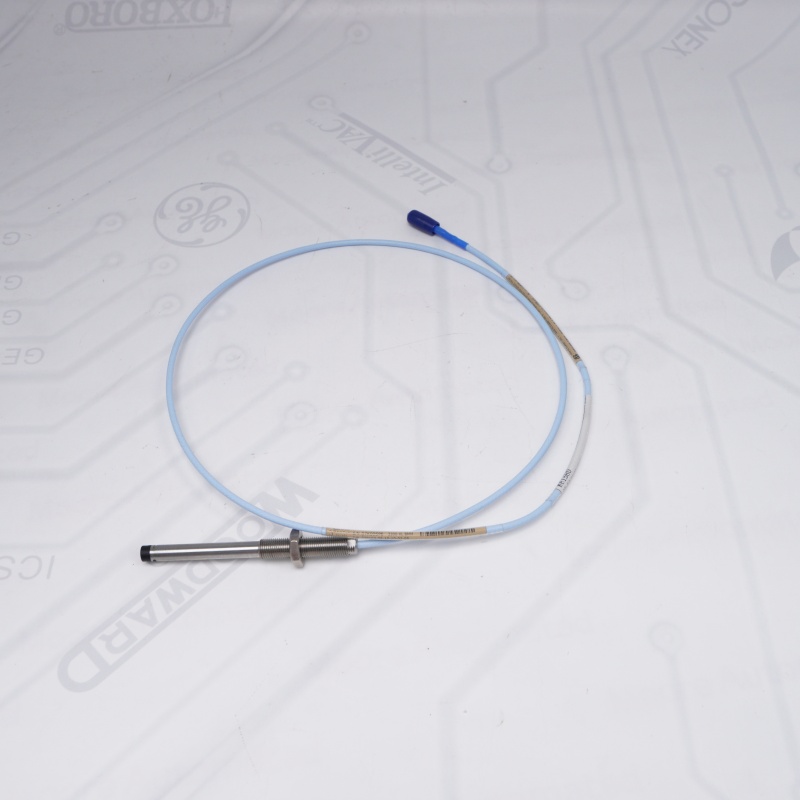
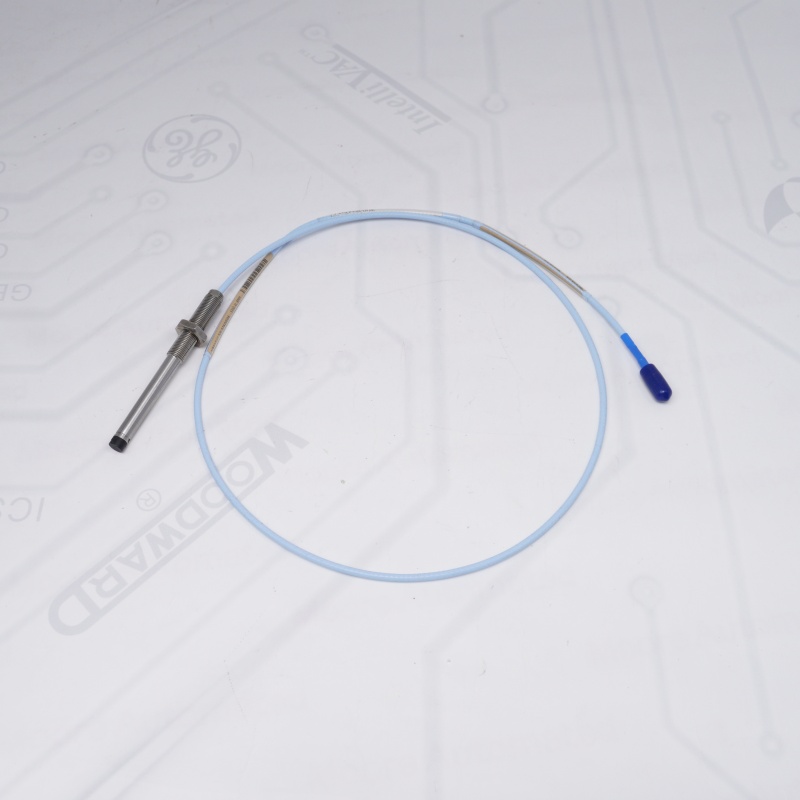
- Bently Nevada 330103-05-10-10-02-05 Family: 3300 XL 8 mm Proximity Transducer System
- Thread Type: M10 x 1 metric thread (Unarmored)
- Unthreaded Length (-05): 50 mm
- Overall Case Length (-10): 100 mm
- Total Cable Length (-10): 1.0 meter (3.3 feet)
- Connector Type (-02): Miniature coaxial ClickLoc connector, standard cable
- Agency Approvals (-05): Multiple Approvals (CSA, ATEX, IECEx)
- Bently Nevada 330103-05-10-10-02-05 Tip Material: Polyphenylene sulfide (PPS)
- Bently Nevada 330103-05-10-10-02-05 Probe Case Material: AISI 303 or 304 stainless steel
- Bently Nevada 330103-05-10-10-02-05 Linear Range: 2.0 mm (80 mils)
- Bently Nevada 330103-05-10-10-02-05 Recommended Gap Setting: 1.27 mm (50 mils)
- Standard Target Material: AISI 4140 steel
- Operating & Storage Temperature: -52°C to +177°C (-62°F to +350°F)
Spare Center Core Specialized Brands
Bently Nevada – Machinery protection systems, 3500 series, and proximity sensors.
Allen-Bradley – ControlLogix, CompactLogix, and SLC 500 PLC systems.
ABB – Symphony Plus, Bailey INFI 90, and industrial DCS modules.
Honeywell – Experion PKS, TDC 3000, and safety control systems.
GE / General Electric – Mark VI/VIe Speedtronic turbine controls and PLC modules.
Siemens – Simatic S5/S7 series PLCs and specialized process controls.
Triconex & Foxboro – Invensys DCS modules and safety fault-tolerant systems.
FAQ
Q1: How does the 330103-05-10-10-02-05 mitigate cross-talk in multi-probe installations?
A1:The 330103-05-10-10-02-05 Proximity Probe utilizes an 8 mm eddy-current probe geometry that generates a localized electromagnetic field at the probe tip. In tightly packed installations, the 330103-05-10-10-02-05 Proximity Probe may experience signal coupling if adjacent probe fields overlap.
To minimize cross-talk for the 330103-05-10-10-02-05 Proximity Probe, the following installation practices are recommended:
Maintain a minimum center-to-center spacing of approximately 40 mm (1.6 in), or greater depending on target geometry
Ensure probe axes are not aligned toward overlapping measurement zones
Use independent Proximitor channels for each 330103-05-10-10-02-05 probe to preserve electrical isolation
Proper mechanical spacing remains the primary mitigation method for cross-talk in 3300 XL systems.
Q2: What chemical compatibility limits apply to the PPS tip of the 330103-05-10-10-02-05?
A2:The 330103-05-10-10-02-05 Proximity Probe features a Polyphenylene Sulfide (PPS) probe tip material designed for high resistance to hydrocarbons and industrial lubricants.
The 330103-05-10-10-02-05 Proximity Probe is generally compatible with:
Mineral-based lubricating oils and greases
Synthetic turbine oils
Petroleum-based hydrocarbons
Ammonia under controlled conditions
However, prolonged exposure of the 330103-05-10-10-02-05 Proximity Probe should be avoided in environments containing:
Strong oxidizing acids
Highly aggressive ketones or halogenated solvents
Final compatibility should always be verified against the specific chemical exposure conditions of the application.
Q3: Why does the 330103-05-10-10-02-05 use a 1.0 m probe cable instead of a continuous long cable?
A3: The Bently Nevada Proximity Probe is part of a modular three-component system consisting of the probe, extension cable, and Proximitor sensor.
The 1.0 m probe cable in the 330103-05-10-10-02-05 is defined to:
Maintain a calibrated electrical capacitance for system linearity
Ensure compatibility with the 3300 XL oscillator/demodulator circuit
Allow field replacement of only the probe assembly without disturbing cabinet wiring
This modular architecture ensures that the Bently Nevada Proximity Probe remains electrically matched within the system calibration chain.
Q4: How is sealing achieved for the 330103-05-10-10-02-05 in pressurized oil environments?
A4:The Bently Nevada Proximity Probe itself does not function as a pressure boundary device and does not include an integrated O-ring seal for process containment.
For oil-lubricated or pressurized machine casings, the Bently Nevada Proximity Probe must be installed using appropriate mounting hardware such as:
Sealed probe housings or mounting fittings
Oil barrier or isolation assemblies compliant with machinery casing requirements
Installation practices aligned with API 670 sealing requirements
Proper system sealing is achieved at the mounting interface, not within the Bently Nevada Proximity Probe body.
Q5: Why is the recommended gap for the 330103-05-10-10-02-05 set to 1.27 mm?
A5: The Bently Nevada Proximity Probe is calibrated to operate optimally at a static bias point of 1.27 mm (50 mils), which is approximately the midpoint of its linear measurement range.
This operating gap ensures that the Bently Nevada Proximity Probe provides:
Maximum symmetrical measurement headroom for positive and negative vibration
Improved linearity across the operating range
Reduced sensitivity to thermal drift effects
The 1.27 mm value represents a calibration reference point rather than a mechanical limit.
Q6: Can the 330103-05-10-10-02-05 measure both shaft vibration and axial position simultaneously?
A6: Yes. The Bently Nevada Proximity Probe produces an output voltage proportional to the probe-to-target gap, which includes both:
A DC component representing static shaft position (gap/axial displacement)
An AC component representing dynamic vibration motion
The Bently Nevada Proximity Probe itself does not separate these components; signal processing is performed by the associated Proximitor system within the 3300 XL architecture.
Q7: What installation constraints apply to the cabling of the 330103-05-10-10-02-05?
A7: The 330103-05-10-10-02-05 uses a non-armored coaxial cable assembly and must be installed to prevent mechanical stress and signal degradation.
Installation requirements include:
Maintaining a minimum bend radius consistent with manufacturer guidelines (typically ≥10× cable diameter)
Avoiding sharp bends or compression points at the machine exit
Using protective conduit or cable routing systems in exposed areas
Preventing mechanical abrasion or crushing along the cable path
Proper routing ensures long-term signal stability of the 330103-05-10-10-02-05.
Q8: What is the frequency response of the 330103-05-10-10-02-05 system?
A8: The 330103-05-10-10-02-05 is part of a system-level measurement chain whose dynamic response is defined by the complete probe–cable–Proximitor configuration.
Typical system bandwidth is:
DC response for static position measurement (0 Hz)
Dynamic frequency response up to approximately 6.5 kHz (-3 dB point)
The effective bandwidth of the 330103-05-10-10-02-05 Proximity Probe is influenced by probe geometry, cable capacitance, and Proximitor demodulation circuitry.
Other Modules
| 3500/32M 149986-02 | 330130-040-00-00 |
| 1900/65A 172323-01 | 330130-040-01-00 |
| 330180-X0-05 | 330180-91-05 |
| 125720-01 | 3500/20 |
| 125760-01 | 3500/45 176449-04 |
| 125768-01 | 3500/60 |
| 128229-01 | 3500/64M |
| 128240-01 | 330103-00-06-10-02-00 |
| 133396-01 | 330106-05-30-10-02-00 |
| 146031-01 | 133442-01 |
| 330103-00-04-10-02-00 | 330180-90-00 |
| 330104-00-06-05-02-00 | 125840-01 |
| 330105-02-12-05-02-00 | 125800-01 |
| 330106-05-30-05-02-00 | 330105-02-12-05-02-05 |
| 330106-05-30-10-02-05 | 330130-080-00-CN |

Email: sales@sparecenter.com